Tuesday, December 24, 2013

26 Batteries and Balancing

Balancing Saga

Went out for a Sunday drive this weekend and about 3 miles in the drive the battery alarms starting going off whenever more than 60 amps (1C) were being pulled from the pack.  Seemed strange since the pack was just charged.  The battery monitors showed several cells with large differences (DIFF Error). The alarms was set to ring at 150mV difference across the sub-packs (6 or 7 cells).  After  the 100A draw, the monitors were showing 250mV differences for several cells.

Well this is what all of the posts on the web about balancing tried to say.  If the cells are not balanced, they will drift and eventually some the charge difference between cells will be enough to be noticed.

Well, we limped home from the Sunday Drive and the cells are returned to a nominal voltage of ~3.2V after a few minutes of rest so I know they were not too discharged, just getting low.

Nonetheless, this has prompted a full manual balancing process.  Picked up a Onxy 235 cell charger and balancer that can charge and balance 4 cells at a time at about 8 amps.  Tried it on one cell, it worked like a champ, tapering off current as the cell approached 3.6V.  Wired up the 4 cell balancing cable and one of the 4 cells had enough difference in charge that it hit the Upper Voltage Limit of 3.6V well before the rest, triggering the alarm.

Onyx 230

So now, the charging process is down to trying to charge 4 at a time but if there is too much variance, resorting to single cell charging to get them all within a few percent of each other.  LiFePO4 batteries have very flat discharge curves, so a tiny voltage variation could equate to several AH of charge.  It seems the only real way to know is to top off each cell until the current draw from charging is quite low (<1A) and  the same cell-to-cell.


Near the end of the charge process, the cell voltage will spike up 0.2V to 3.6V. The charger is set to 3.6V so as soon as the cell hits that, the charging will safely stop.
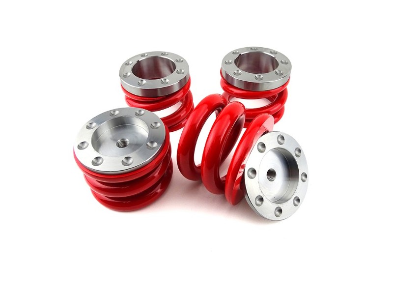
Springs

Finally completed the Hi-Lo installs.  The fronts and rears are in and set.  Final right height, based on the factory spec of 53 inches at the roof, is 9.75" at the lower sill seam near the rear wheel.  The back is about 0.5" higher than the front which is normal for Classic Minis.  Looks good, handles well, and the ride is quite smooth now.  At this height there is sufficient compression at the springs when the wheels are off the ground to keep the springs in place.  Much lower and larger upper bump-stops would be needed.

Blower

A new blower was installed to cool the motor.   The leaf-blower, though effective was just too loud.  The new blower is Jabsco, 3" Blower, Flexmount, 105 CFM,   Much quieter and about the same CFM as the leaf blower.  Mounted much nicer also.

Computer Work

The work continues to refine the software running on the Arduinos.  Was able to connect the battery monitor Arduino to the Mini's fuel gauge so the gauge shows charge level now.   Used one of the PWM outputs on the Arduino (Pin 9) to drive the following circuit.


The PWM was set to a range of 0-205 to map from 0%-100% of the charge.  100% is still set to 48AH even though the batteries are 60AH cells.  This leaves 20% of margin.

Also added some more error messages to the Motor monitor to indicate different situations like over temp or low voltage or over current.

Wash and Wear

Wipers and Washers

For a bit of a distraction this weekend, I dove into the windscreen wipers and washers.  The wipers were operational, but very slow.  The washer was an unknown situation.

First was the washer motor.  It is shown below behind the washer bottle.  The motor was pulling current but would not spin.   It was simple to disassemble, just a few tabs to bend back.  It didn't look too bad inside for a 40 year electric motor that has been exposed to moisture its whole life.  The motor was frozen but a little persuasion and it spun free.  A few drops of lithium grease on the shaft and it was humming away.  The pump is in decent shape and just needed a little cleanup of the o-ring.

The washer bottle was another story.  It had a 4" crack on the back side where it slides into the mounting bracket.  Well, a little fiber-glass patch work and it was water tight and probably stronger than the original plastic.  Reasssembled the system system and water sprayed out of both nozzles.  Two issues still:

  • The spray jets are positioned right under the wiper arms and thus very little water gets to the windscreen unless the wipers are going.    
  • There is no switch to activate the washers.  The wire is behind the dash, but it is not clear where the switch is or was.  Some Minis have the washer switch on the turn-indicator stalk, but Jane's stalk is already full with high-beams and the horn.  A new switch will have to be added to the dash


Black Washer Motor behind yellowish washer reservoir. 


The Wiper motor shown here was mostly just gummed up.  After opening it, cleaning out the 40 year old grease (it wasn't very greasy anymore) and trying to clean-off as much exterior grime as possible, it now spins great with two speeds and automatic parking.  The park switch was a bit sensitive to how the connectors were attached, but after a small adjustment of the inner switch connection, the parking function works as expected.  There is a plunger that is pushed from the motor shaft that separates a contact in park-switch when the motor is in the parked position, stopping its rotation.  One interesting observation about the wiper motor.  The cover holds the permanent magnets and is not marked.  It has two possible orientations, 180 degrees apart.  In one orientation, the motor would spin the drive gear counter-clockwise.  In the other, clockwise (the proper direction).  Of course, it took two tries to figure this out.

Battery Monitoring

The battery monitor has advanced quite a bit.  Shown here is the four CellLog 8M based monitor.  The CellLogs are mounted on a board from ElectricPorsche.ca.  Robin at Electric Porsche has designed this board which was a perfect fit for Jane's needs.  It now monitors all 26 cells and activates a loud piezo buzzer if any of the cells are out of range.  I currently have them set at 2.50V - 3.55V as the normal range.  The looping wiring on the right side is setup to assure that if a CellLog fails or a wire comes loose, the alarm will sound.  The CellLogs keep the 4 relays closed when on and not-alarming.  If a CellLog goes off or alarms, it ceases to maintain the closed relay and the buzzer is sounded.    This system mounted in the boot, on the boot lid, so it folds down quite nicely for easy viewing.  Also, I moved the 600A contactor back to the boot today so that it would not be exposed to the elements under the hood.  Was able to use the electric fuel-pumps power to activate the contactor when the 12V system is turned on with the ignition key.  Just one of the many clean-up things that needed to be taken care of.

Charging update:  With the CellLogs operating now, I have turned down the charger to an 86V terminating voltage, which is 3.3V per cell.  The charger is designed to switch to constant voltage at that point until the current drops to about 1 amp.  This is not the fastest way to charge.  When the charger was set to 91V, a few of the cells would exceed the 3.55V alarm voltage before the pack reach 91V (26 x 3.5V).  Wanting to be conservative, I opted for a slower charge at a lower constant voltage, which should be easier on the cells.  After a couple of charge cycles with this new setup, all of the cells are staying within 30 mV of each other.  LiFePO4 batteries have very steep voltage curves when they near the end of the charge cycle, so as the few slightly fuller cells got near the end of the charge, they would shoot up the voltage curve triggering the out-of-range alarm while the rest were still taking in the last few amp-hours.

Sunday, December 8, 2013

Springs

New Springs on the rear

Replaced the rear, very dead rubber cones with new springs today.  The springs are called the SRP-200 (Red, firm).  I started in the back, since most say it is simpler.  However, removing the old springs from the struts turned into a 2 hour job of cutting, chopping, heating, grinding, sawing and a few other choice actions.

This is what Jane's struts looked like.  The top one has the remnants of the old rubber spring.  The bottom one has had it cut away with a angle grinder.


Here are the new springs.  (C-SRP200 from SRacer).


Also, realized that the knuckle joints on the structs were in need to new protective covers during all of this.  The knuckle joint provides rotational flexibility for the strut. Shown here, the top seats in the frame and the strut slides on the post at the bottom.


The front left spring was rather easy to replace.  It required just one trip to Home Depot to get the parts to build a spring compressor.  A 2' piece of 1/2" all-thread, some nuts, a few washers, and for $7, a Mini spring compressor was born.  Worked like a champ.  Removing the upper suspension arm was easy by simple removing the cover plate from the shaft for the arm, taking off the two 3/4 nuts on each end and simply pulling the shaft out.  Took all of 10 minutes.  Once the new spring were compressed, the arm went right back in place.   The front knuckle joints were in good shape, so they just got repacked with grease and sealed-up.

The old rubber spring was a mess but it did separate from the trumpet much better than the rear ones.  A few hits with an old chisel and the spring separated from the trumpet strut.

The right side is going to be trickier since the new electric motor sits right in front of the upper suspension arms shaft cover plate.  Looks like the motor is going to have to be raised out of the way.  

With the new springs in, the front-end sits about 2 inches higher than the rear now.  Makes for an interesting look.  Hi-Los are on order to bring down the front and level the whole car.  A Hi-Lo is just a adjustable strut that can be extended or retracted to raise or lower the suspension.  I guess the reduced weight of the engine missing, does not compress the springs enough to keep things level.


Saturday, November 9, 2013

Seeing is believing

LED Dashboard Lights

After an evening drive the other night, we realized that being able to see the speedometer in the dark is useful.  The tiny LLB987 bulbs, which may be 40 years old, just don't put out much light.  Well there are LED equivalents available from www.v12s.com which are perfect.  Not only do they fit well, but they produce a nice white light, much brighter than the old bulbs.


See for yourself.  This photo shows the difference.  The left side bulb was changed to the new LED version, the right is still the old incandescent type.  The fuel gauge may be a bit too bright, but that will be good once it is connected to the battery monitoring system.

Tomorrow, new springs for the suspension which means pulling out the old rubber cone-type (sometimes call donuts) springs and installing heavy duty real steel springs.  This should vastly improve the ride.  Currently, it feels like a bicycle, where every crack, bump and pebble is felt, since the rubber cones are fully compressed and there is no travel available.   No telling how old the current rubber cones are but they are only expected to last 5-7 years and given the lack of compression available, they are well past their life expectancy.


Sunday, October 20, 2013

It keeps getting better

Covering some real ground

With the full battery pack and a instrumentation package up and running, we are now going for longer drives.  Yesterday, we covered over 10 miles on a single charge.

The charging system is working great.  Two charges, both tied to the 220V input.  One is the 1500W 91V Lithium Ion charger for the drive battery and the other a 120W 12V charger for the system battery.  Since both are automatic, they shutoff independently when charging is complete.  I have the 220V outlet on a timer just to be safe.

Instrumentation Pack

Here is a the roughed-out instrumentation pack.  This will be mounted behind the dashboard once it is installed.


1) On the left are 4 CellLog8M battery monitors.  These are set to alarm if any of the individual cells go out of range.  Currently I have them set tightly at [3.0V - 3.6V].  Charging is set to 91V which should be 3.5V/cell on average, so any major drift will be detected.  The cells have sagged below 3.0V on a recent hill climb, but recovered to 3.2 very quickly once the road leveled off.  

2) The top-right rectangular LCD is one Arduino Uno which is connected via the CAN Bus to the Kelly Controller.  It monitors: 
  • Top Row: RPM, Battery Pack Voltage, Controller Temperature
  • Bottom Row: Drive/Reverse, Calculated Speed (Assuming 2nd Gear for now), Motor Amps, Motor Temperature
3)  The lower LCD is another Arduino which is measures battery current through a 600A/75mV shunt.  It is power separately from the drive battery pack via a 12V adapter.  This keeps the battery system isolated from the rest of the car's 12V electrical system.  This Arduino is always on and maintains a running count of the amp-hours consumed.   The shunt is installed at the battery negative terminal to eliminate noise from the motor and to allow for monitoring charge going into the battery from either the charger or from the motor's regeneration braking.

In a quick experiment, after a 5 mile drive, I then connected the charger.  The Amp-Hour counter returned to within 3% of full.  Please note, I have not calibrated the system yet, so this is very promising.  The system is using an Analog Devices AD8210 Shunt monitor to measure the voltage drop across the shunt.  It is wired with a split-supply configuration, so 0 Amps = 2.5V going into the A/D on the Arduino.  This setup should yield about 1A precision on counting amp-hours.  Given the 20% DoD (depth of discharge) limit, this should provide plenty of margin.

Controller settings

Now that there is decent current monitoring, we tweaked the Kelly KHB72701 controller settings a bit to see if there is a bit more power available.  During the drives yesterday, The battery current never exceeded 200A and the motor current peaked at about 300A.  The spec on the motor is a max of 420A for 1 minute and the batteries should be capable of 400A-600A for short bursts since they are 60AH packs and there are several reports of people safely pulling 8C-10C.  Batteries are rated in terms of multiples of the AH measurement, so a 8C battery can deliver 8x60AH for a short burst. 

With motor blower providing plenty of cooling, he motor's temp peaked about 55C.

New Settings:  
  • Throttle Range 5%-80% (this is a mapping to the mechanical throttle position).
  • Max Motor Current 90% (this is of the controller max of 700A --> 455A)
  • Max Battery Current 100% (700A)
  • Undervoltage (Controller will start to cut back power draw at 110% of this value): 68V (cut-back at 74.8V, or 2.87V)
  • Overvoltage (Controller will limit regeneration if voltage exceeds this): 90V
  • Throttle Ramp: 4 (How fast it will ramp up acceleration)
  • Regeneration: Off 
Off for another test drive to the grocery store....


Sunday, October 6, 2013

Starting to see some encouraging signs

First Extended Drive

Today, we headed out on a extended drive.  Not knowing the real efficiency of the car (miles/charge), it is going to take some testing to become comfortable with the nominal range.  The Amp-Hour meter that is currently connected does not retain its values after a power cycle, so it is not a great fuel gauge.  More on that later.....

It was a sunny day here, about 65 degrees, so a perfect day for test drives.  Earlier in the week, I did a 4 mile run around the flat part of the neighborhood and the batteries only required about 30 minutes to recharge fully.  Today, we drove for 8 miles with some hills.  The batteries still read about 85V but since the drop off near the end of the charge is fast, I am hesitant to let them get too low.  Well after a 7.5 mile drive, they took about an hour with the 16A charger to return to 91V (the current target charge level).  This was the previous charge level so it should represent a reasonable replacement energy measurement.

Based on these estimates, the car averaged about 180 Watt-Hours/mile.  Right in the expected range of 150-200.  With a conservative 80% usable capacity, this should equate to 22 miles of range per charge.  A GPS was used to track distance, but a more accurate charge timer is needed to estimate the actual Amp-Hours that are being put into the batteries, or taken out with the a better amp-hour meter.

Here is the boot with the batteries in position.  Not a lot of extra room  The brown and blue wires are the battery monitors which make sure that none of the cells deviate too much.  The next step will be to route these up to the dashboard so the driver can monitor the battery condition.  The large blue connector is the charger connection.  The charger will be mounted to the left of the pack.  The large (red) 12 battery is powering all of the electronics in the car (lights, radio, controller, fans)


Cooling

The motor coil temps, as reported over the CAN bus from the Kelly controller is running between 80C-90C after a couple of miles.  This is well below the limit of 145C but still on the high side.  The internal fan on the motor has two issues:
  1. It does move a lot of air - @2,000 RPM, I could barely feel any air leaving the motor.
  2. It does not cool when the motor is not spinning. 
A supplemental fan is needed and I found a 12V marine exhaust fan that moves a lot of air.  The challenge is how to duct the fan into the motor in the tiny Mini engine compartment.  I tried a Rube-Goldberg solution today using 4" flexible ducts but there is just not enough room at the end of the motor (where the internal fan draws air) to route the ducts.

The Plan:  Bring in 1" hoses (probably two) into the fan housing on the motor, from the top to push more air through the motor.    The challenge: How to plumb the 4" fan down to a couple of 1" hoses through a manifold.  The air is moved from one end of the motor to the other, horizontally.  There are large vents in the housing on the shaft end, so if enough air can be pushed into the fan end, it should push on through, providing much better cooling.


Thursday, October 3, 2013

First test of the Full Battery Pack

We headed out around the block with the new 84V 60AH battery pack.  Starting out in 2nd gear to keep things gentle, Jane climbed our hill with little hesitation.  Next we headed for the short flat stretch of street around the corner and in third gear, she got right up to speed.  Here is a video of us returning home.   You will see the pack mounted in the boot along with the battery monitor leads.


Even under the full hill climb, the pack only sagged to 80V, still close to 3.1V per cell.

Next - Clean up.  Lots of cables and mountings to sort through.   However, it is a great motivator to be able to see it all coming together.  Also, a quick run down the to the non-hilly part of the neighborhood for a real speed test.