Sunday, September 29, 2013

Battery Time

The batteries arrived and this opens an entirely new chapter in design and learning.  Not only is there the mechanical design elements of assembling and installing the battery pack, there are the safety challenges. Compared to gasoline, I believe batteries are safer and easier to work with, but society's false sense of security with gasoline causes some initial concerns.

The batteries of choice for Jane are the CALB CA60FI.  These were introduced last year and the reviews are all very positive.  These were sourced from Shift-EV in Albany Oregon.  Kirk is a true expert on EV conversions.


The chemistry is LiFePO4 (Lithium Iron Phosphate) and these offer 60AH  at 3.2V nominal.  The pack will consist of 26 of these in series providing a nominal pack voltage of 83V.  At a 80% depth of discharge assumption, these cells will provide 48AH @ 83V or just shy of 4 KWH.  The Kelly Controller is limited to 90V input voltage, so  this provide a little margin, but should still be sufficient voltage for the motor to achieve 3,600 RPM under load.   Based on the best gear ratio calculations, in 4th gear, Jane will cruise comfortably at 55 MPH.  3rd Gear will yield 45 MPH.  More than fast enough for this car and any city driving.  There is an option final drive gear (3.44:1 --> 2.76:1) which will pull in another 13 MPH at the electric red-line.

Pack weight=26 x 4.45 lbs = 116 lbs.

If you want to see the detailed calculations, here is a spreadsheet (Called Vehicle Calculations) with the best-guesses for performance.

Charger

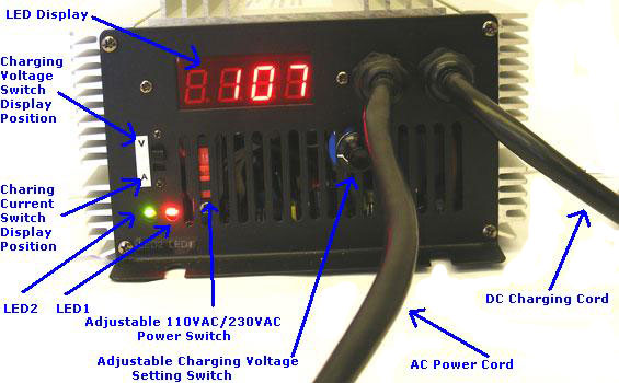
Another major component for the battery pack is the charger.  We selected an automatic, adjustable voltage charger from BatterySpace which provides 16A and 1,500 Watts since there is still much debate over the best charging process to maximize longevity of the battery pack.  The first charge cycle completed successfully set at 91V and the charger performed as expected, shutting off when the pack reached terminal voltage.  This is plugged into a 6 hour mechanical timer and a 220V 30A outlet in the garage.  It will get mounted in Jane's boot and eventually a simple cord is all that will have to be plugged in to "fill her up".
This charger will fully charge an 80% depleted pack in about 5 hours.  The CALB cells can take a faster charge, but there are cascading effects from increasing the charger power such as more heat, more battery wear-n-tear, larger cables and bigger power sources.


Battery Monitor

And the final critical element of the battery pack is the monitoring system.  With LiFePO4 batteries, maintaining them within the proper voltage range is critical to prevent damage.  There are many opinions on how best to do this but it is clear that the tighter the range of voltages, the less stress on the pack.  Initially, the system will be set to keep the cells between 3.0V (discharged)  and 3.5V (charging), though others say the window can be slightly larger.  Battery Management Systems range in price up to thousands of dollars, depending of the size and number of cells in the pack.  Since the battery is the most expensive element of the EV drive train, it makes sense to monitor and manage it diligently.

For Jane's initial BMS system, passive cell monitors will be used to report and alarm if a cell goes outside of the target range.  The driver will have to respond appropriately based on the situation and severity of the deviation.  Not terribly different than the check-engine or over-temperature light on a gas car.  A driver can choose to ignore it but damage may occur.


The CellLog 8M is a clever device.  It provides monitoring for up to 8 cells and alarm capability for High Voltage, Low Voltage or if there is too much variation between the cells.  It will take 4 of these to monitor the 26 cells (2x6 and 2x7).  There is an minor annoyance with these devices in that they draw less power from cells 7 and 8, causing those to discharge at a slightly slower rate than the first 6 cells.  Given Jane's configuration, this will only impact 2 cells which may need to be balanced periodically to bring them back in line with the rest of the pack.  The four CellLogs will be mounted in a cluster on the dashboard so the driver can quickly see all 26 cell voltage values if an alarm occurs.

The last component in the monitoring system is the AH meter from Elite Power (600A 90V Combo Meter).  This will act as a fuel gauge and provide a count of the Amp-Hours (AH) drawn from the batteries. Using a 600A 75mv shunt on the negative side of the battery, this meter will count the actual cumulative power (AH) fed into the controller.   With LiFePO4 batteries, voltage is not a good indicator of State-of-Charge (how much energy is still available from the cell), so using AH counting will provide the most accurate fuel gauge.  It will take some verification and experimenting to map AH to overall state-of-charge.    More on that to follow...


Elite Power Meter

Shunt

Finally, the EVALBUM page is up for Jane.  Not all of the details yet, but a great gateway to other electric vehicles.   Be sure to check it out....   http://www.evalbum.com/4768


Thursday, August 29, 2013

Instrumentation

A big part of Electric Vehicles is the instrumentation that is possible with a electric motor.  There are some generic systems that can monitor basic functionality of the system and display it on a small LCD, but as with most of the elements of Jane, this too is going to be have to custom built.

The good news is there are now off-shelf electronics available that can be utilized.

Available information

The Kelly KHB72701 controller has an optional CAN bus.  This provides an industry standard bus that allows a computer to communicate with the controller.  The controller has a wide range of data available via the CAN bus.

Available Data includes
1) Voltages: Batteries, controller supply, accelerator sensor
2) Motor Specs: RPM, Motor current and Phase Width Modulator (PWM) value
3) Temperatures: Controller and Motor
4) Switch Settings: Reverse & accelerator micro-switch

Notes: The CAN BUS is internally terminated within the Kelly Controller.

All that is needed is small computer than can read and display this.

Arduino

The Arduino platform is a great development system.  There are a number of controllers available along with accessory boards that mount directly on the controller, allowing for easy to configure HW solution.  Also, many libraries exist to help jump start development.
Useful links:  
Main Arduino Page  - We are using an Arduino Uno

These three boards mount together and will the main controller for Jane.

Software

Here are the project specific files for the Sketch that generates the dashboard below.  Google Drive Link


I'll have to dust off my software skills to start work on the C code for the Arduino board.  Luckily it won't take much to have it perform basic dashboard functions.  The key data I would like to display realtime is:
Motor RPM --> which can be used to calculate vehicle speed if the gear is known.
Motor and Controller Temperatures --> Need to make sure nothing is getting too hot
Motor Amps as reported by the controller
Battery Amps as measured by a current shunt
Drive/Reverse - To confirm the electronic Reverse is working
Controller Errors --> Just in case something goes wrong

Here is a picture of the prototype display 

Battery Current Measurement

The real measure of power and efficiency requires accurate battery voltage and current measurements.  The controller does not report battery current so a current is installed on the ground side of the power going to the controller.  Using the negative side helps eliminate common mode voltage since the motor battery is not connect to the 12V battery which powers the controller.  The shunt is a low resistance resistor that will generate 75mV from a current of 600A.

The current plan is to install a Amp-Hour (AH)  & Current meter like this meter from Elite 600A-90V Digital Dual Display.  It will provide instantaneous readings plus it offers some alarm capability.


Saturday, July 20, 2013

Power, gears and hills

Now we are rolling along

With CV joints behaving as they should, the real testing is starting.

After dozens of runs up and down the hill outside our house, my confidence is building in Jane.  Playing it safe, I always start out heading uphill first so that if a problem occurs, gravity will get me home.

At this point the three Lead-Acid batteries easily go 2 miles.  Instrumenting the motor is a going to be key. So far there are two gauges: Motor (or Phase) current and Battery Current.   The relationship between these is dependent on motor speed and load, which has to be estimated based on the speedometer and the current gear.

I have found that there is not a single level road nearby.  This actually creates problems since any incline or decline in the street impacts the power needed to move the car.

So far, the motor current (varies dramatically based on controller settings) peaks around 420 amps (60% of the controller rating of 700A).  The Motor current meter is suspect since is jumps to 20% under the lightest load which is equivalent to 140A (20% of the controller's max amp rating).  It seems like 140A should be delivering quite a bit a power.

Battery current has only peaked at 300A which is great to see given the target battery pack is rated at 600A so this will be well below the limit, extending the overall lifetime of the batteries.

3rd Gear looks to be the best in-city gear.  During yesterday's testing, it cruised comfortably at 20 mph with the 36V battery pack.  The target pack is going to be 84V and speed scales linearly with volts, so 3rd gear should yield >40 mph.

It is a real challenge to understand how much power is actually being used.  The battery volts and amps can be multiplied to compute Watts going into the system.  The motor and controller have a combined efficiency of about 75% (conservative) so that should yield power out of the motor.  Given all of the losses in the drive train and air resistance, the predicted speed based on power should be close.  Here is one example of the power model.   From this at 30 kmh (about 19 mph) the motor should be delivering 2500 W (3.35 HP 745 Watts in a HP).  This should equate to about 3,300 W from the battery (@75% system efficiency).  At 34V, I would expect about 100A of battery current.  This comes close to what the meter reads.


Speed (km/h) 10 20 30 40 50 60
(m/s) 2.8 5.6 8.3 11.1 13.9 16.7
ForceOfAirResistance (N) 2.6 10.6 23.8 42.2 66.0 95.0
ForceOfIncline (N) 127 127 127 127 127 127
ForceOfRollingResistance (N) 115 115 115 115 115 115
TotalDrag (N) 245 253 266 284 308 337
Power to Maintain Speed (W) 756 1560 2462 3511 4755 6244


I would welcome feedback on the calculations and logic.  Next is to figure out total range based on the Watt-Hour capacity of the batteries.  The Kelly Controller has a CAN bus available and will report some useful information such as motor phase current and voltage, motor and controller temperatures, motor RPMs and battery voltage.  The current plan is to program an Arduino controller to read this data along with other system data (battery status, battery current and cell voltage).  The Arduino will act as the car's computer and display for the driver key performance data.  A bit of modern technology for a 40 year old car.


Sunday, July 7, 2013

Getting to the bottom on the Thump

The Thumping diagnosed

After a great 2 hour session of trying to debug why Jane would thump loudly, lose power and stop.  It seemed like the controller was cutting power to the motor for some unexplained reason.  We ran it for 4 full minutes on jack stands while applying the brakes to simulate a reasonable load.  The motor was working as hard as it does on the local hills The brakes could apply enough to stall the motor but the thumping never occurred on the stands.  The mystery: what was different on the street versus on the stands.

Well today, first thing, I swapped out the 18V power supply that powers the Kelly KHB72701 controller.  Switched it back to a an old AC adapter with an 400W inverter, very Rube Goldberg.  First 6 inches up the drive and the thumping returned, as bad as ever.

So I opened the hood, had Carly gently apply some gas while I watched the drive shafts.  Sure enough, the driver side inner CV joint was slipping.  I could see the inner shaft rotate from the differential while the outer shaft slipped out about an 1/8" and then jumped back.  This was accompanied by the thumping sound.  Aha.

Here is a picture of what the CV joint looks like. 

When the car is elevated and the wheels drop, a few of the balls are pushed into the hub.  However, on level ground, the balls move out to the edge (like the ones on the left above).  When all six are near the edge, the slightest of force will cause all of them to slip out of their groove, only to jump back into the next slot, ready to thump again.  If the joint is at an angle, 1 or more of the balls will be deep in its groove and unable to slip.

As with anything, once you know what is it, it is easy to find information.  The following video shows another Mini having the exact same problem.


Jane was not thumping quite this bad, was was still violent.

Root Cause

Looking underneath, it became obvious the motor had slipped a bit forward.  Due to the electric, the motor only has one mount, the horizontal stabilizer and a strap holding it to the frame.  The strap allowed the  passenger side of the motor to slide forward about 1 inch, which caused the CV joint to align almost straight from the differential to the wheel hub when off the stands.  Well, it seems like having a constant angle on the CV joint actually prevents all of the balls from being on the edge of the grooves, where the slipping (groove jumping) can occur.  When the joint is perfectly straight, it is quite easy to see how the slipping could occur.  The horizontal angle was straight due to the engine misalignment and  when the car was lowered, the vertical angle would also line up near zero.  While on the stands, there was always a good angle at the CV joint, so slipping was impossible, explaining why the above test revealed nothing.  It is not logical that the controller would know whether the wheels were up and it seems like logic prevails, again.

Solution

So it is time to figure out a better mount for the motor which will prevent the movement.  With the motor sitting in the right position, the drive shafts look symmetric which is a great sign including a permanent angle on the CV joints.  Now, just to engineer a good mount.  With the motor out of position, one shaft was fairly straight (limited angle on the CV) and the other had quite a bit of angle.  Symmetry is a good thing.

If the new mount works, battery testing will resume.  A 600A ammeter is on its way.  This will allow for real current monitoring.  The Kelly Controller provides a 0%-100% current scale, but even under minimal load, it jumps to 20% and seem fairly rough at measuring phase current (Motor current).  The new ammeter will report battery current which when multiplied by the voltage will yield instantaneous power, the real indicator of how things are working.  I am intrigued to be working with such large currents, when most of my career has been spent in the milliamp range of the scale.  A 600A fuse is impressive.


Friday, July 5, 2013

First long drive to get fireworks on July-4

I say adventure, they say it's no fun to push a car up a hill.


We took Jane out to go get our July-4 fireworks at the nearest (1 mile away) fireworks stand.  Well it was mostly downhill to the stand, so that went well.  On the way home, things were going well and then we hit the first reasonable incline.  The motor cut-out but then was right back, basically pulsing with a thump-sound.

We pulled to the side, to check things and then started out again, only to have it repeat.  Every time I pushed on the accelerator, it would thump and not go.  Everything under the bonnet looked OK, no error indicators on the controller, batteries seemed to have sufficient power.  No logical explanation.  I had changed a couple of settings in the controller that morning.

So we hopped out and started to push it up the hill.  Luckily a neighbor was driving by and a stranger both joined in for the steepest part of the hill.  We made it home and everyone was a little winded.


Today, I spent with the car up on stands, just testing.  On the stands it performed well, spinning the wheels up to 35 mph in 4th, about 2,100 RPM.  This right inline with the estimates based on 36 volts of batteries with minimal loading.  Reset the settings that were changed yesterday.

So I figured, I could lower it back down and see.  The thumping returned just trying to back-out of the drive.  Back up on the stands.  No thumping.  Back-down and it seems to be running well again.  Up the steep hill with no problems.  Makes no sense.  Recharging the batteries now and then I'll head out for around block testing again.  

So far it's made it 2 miles on a charge with reasonable hills.  Given the quality of the three lead-acid test batteries I've been using, the best I can estimate is with the 60AH of LiFePo4 @ 84V that are planned, the car should be 15-20 miles on a charge. Eventually, it will be easy to double the battery pack to double the range.  Just a cost management situation at this point.  In a small town, 15 miles should be good for a day where nothing is much farther than 3 miles away.  Based on the charger, it should be able to recharge in about 4 hours.  More on that in near future.


This is a GPS plot of the 2 mile journey   Blue Line is speed (15-20 downhill, 7-8 up hill in 2nd gear).  The  gold line is the grade of the road.  You see the hills around the 10% range.  Fairly steep for an electric.  The Greenline is elevation (Green scale on the left).  A 5% grade requires twice the power.

Tuesday, July 2, 2013

Lots of experimenting

No pictures today, but a few interesting insights from the first few runs around the block.


Living on a fairly steep hill, we have been testing quite a bit going up the hill and then coasting back down.  Not wanting to get stranded at the bottom of the hill entering the neighborhood, it is critical that Jane can make it back home.  So far, it powers right up the 150 yard hill with little hesitation.  Still limited to about 1,200 RPM due to the lead-acid batteries being used for testing.  Three decent used batteries in series is holding  steady at 34-35 volts under load.  The Kelly controller provides a ammeter signal for an analog meter that reads as a percent of "controller maximum motor current".  The car climbs the hill at about 280 amps (40% of 700 amps maximum)  at the motor.  The motor is rates at 125A continuous and 450A maximum for 1 minute, so this seems within the reasonable range for 45 second hill climb.  We did 4 climbs yesterday before the batteries started to dip.  The motor was warm to the touch, but not hot.  The motor's operating max winding temperature is 145C and has a thermistor connected to the controller which should shut things down if it gets close to this temperature.  On a minor uphill grade, the motor is pulling about 140A at maximum RPM.  There are no flat roads in the neighborhood, so until we have enough confidence that Jane can make it home, hill testing is all that is available.

Power Booster

The Kelly controller is recommended to run above 18V, isolated from the main batteries.  The standard starting battery is still in the car to power the electronics (radio, lights, blinkers) but only provides ~12V.  Amazon sells a voltage booster based on the TI LM2577 Link for about $9.  This worked great and now the controller is powered right at 25V.  There are numerous comments that the higher supply voltage enables the controller to operate better, but I am not sure exactly how.

Battery Selection

The search and calculations continue regarding battery choice.  The CALB CA60FI are leading the pack.  They can provide 10C which means a pack will be able to supply 600A for 30-60 seconds.  The motors 1 minute maximum rating is 600A into the controller, so this seems like a good match.  Also, the CALB packs are carried by a number of resellers which adds to their credibility.  The remaining questions revolves around the total target voltage for the battery system.  The default choice is 77V (nominal) which would be 24 packs a 3.2V each.  However, every volt yields about 50 additional RPM so a 84V system will allow the motor to generate additional 350 RPM which in 3rd gear equates to about an additional 5 MPH.  Not a big deal but could mean the different between 35 mph and 40 mph, which even for city driving would be nice.  In 4th gear, it is almost a 7 mph difference.  Now pushing the limits up to 90V (2 more packs) will yield yet another 300 additional rpm and few more mph.  With the lower gearing, it may not be too big of deal.  Putting the full battery system into service at the same time enables the packs to age equally and that should help maintain balance.

A few more experiments this weekend and then it will be time to decide.


Sunday, June 23, 2013

Now we are motoring

Well this weekend was one of actual driving the electric Mini.  The motor is mounted, the stabilizer bar connected, the controller, inverter, 18 V supply, throttle and 12 V system are all connected and operational.

So we backed out of the garage.  The electric reverse switch is a wonderful feature.  Just leave the car in 2nd gear and the motor can change direction with a flick of switch.


Heading up the hill.  No Smell, No fumes, No Gas


At the top of hill, it was quick turn-around and then coasting down at about 20 MPH.  A good test of the transmission.  Regeneration is still turned off at this point.  


Then we turned around again and headed back up for another test.  

Observations for the day
  1. Electrics are quiet and you can really hear the radio and birds.
  2. 25 Volts is only good for about 10 miles an hour on level ground in 2nd.  I figure we are only getting 1000 RPM.  The current meter reports about 300 amps (probably close to 33 ft-lbs of torque).  The original 988 could generate 52 ft-lbs @ 2700 RPM.  With the real batteries, the electric should easily surpass this.
  3. Going up and down the block gets a little boring after awhile.  However, with limited battery capacity, it would not be wise to stray too far from home, especially where you can't coast all the way home.
Next steps.... Time to size and purchase the real batteries - Probably 26 LiIon packs... More to come....