Fitting the pieces together

This is the electric motor (ME0913) mounted to the adapter plate mounted to the flywheel housing connected to the gearbox. Some preliminary measurements indicate that this should fit in the engine compartment without having to make any major modifications, a key goal and reason for selecting this motor.

From the top, you can see the full gear train of the transmission. The differential is the protruding mechanism at the bottom, nearest my left foot. The CV joints and axles will connect to that.

A new thrust washer was also needed to tighten up the tolerances on the float for the idler gear (the one the primary gear mates to). The spec is about 0.003" of float (movement back and forth) and with the new thrush washer, the float is right at 0.002". Most of the advice on the web is to be very close to 0.003", so this should be just right. Thrust washers only come in 0.005 increments or so, there is not a lot of options.
The original primary gear is shown right in the center with its retaining bolt holding it to the shaft of the motor. The shaft adapter (7/8") was turned to press fit into the primary gear with its roughly 1.5" bore along with a 3/16 key. Then a hole was drilled through the spline of the primary gear to lock it to the shaft adapter with a 3/8" bolt. We also installed a new oil seal for the primary gear, though there should not be much oil around that gear since it does not have any bearings now.
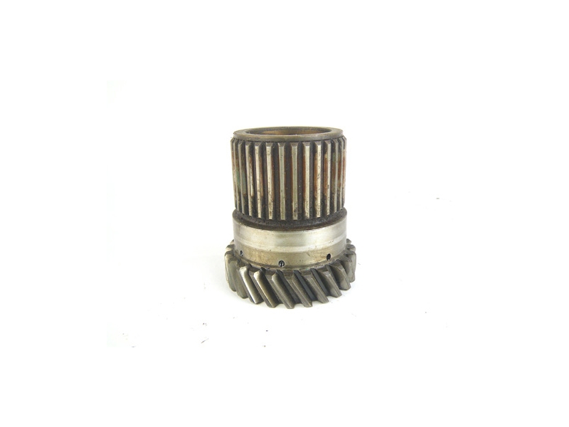 |
| This is the primary gear. The splines that were drilled along the top end of the gear. |
Next steps... cut and drill covers the gear box, then order up the controller
Drivability
In an effort to keep Jane driving during the conversion, the clutch slave cylinder was rebuilt. The old internal parts looked to be 40 years old and the rubber seals were shot. This explained why the clutch was so spongy. Carly noticed immediately how much firmer the clutch feels and how the contact point is much closer to the top of the range of travel. Also, it doesn't bottom-out any longer and shifts easily with no gear grinding. It's the small things....
.
Controller Thoughts
At this point, I am thinking of using Kelly KBH72701 which is a 72 volt 700 amp BLDC controller. The biggest question at this point is whether we should go with a 96 volt model to squeak out a few more RPMs. The maximum RPMs of the motor are determined by the voltage at a rate of approximate 50 RPM/volt. The ME0913 is rated @ 5,000. Our overall strategy is not to operate any key component at or near its limit to extend its life and reliability.
Given then gear ratio and 10" wheels of the Mini, this tables shows the speed of the car in different gears and motor RPMs.
| RPMS | 1st | 2nd | 3rd | 4th |
| 1000 | 5 | 7 | 12 | 16 |
| 2000 | 9 | 15 | 23 | 33 |
| 3000 | 14 | 22 | 35 | 49 |
| 4000 | 19 | 30 | 46 | 66 |
| 5000 | 23 | 37 | 58 | 82 |
Courtesy of Guess-Works
At 72 volts, the motor will top out around 3,500 RPM which in 4th gear will be about 55 MPH. Probably faster than anyone wants to go in Jane. The motor torque will be limited by the amperage of the controller. The motor is spec'ed at 420 AMPs (for 1 minute) and this controller can deliver up to 700A, so there is plenty of headroom. This will help not overhead the controller.
The motor's torque is computed by Amps x 0.15 (NM/controller amp). At maximum current (600 battery amps into the controller, this will equate to 90 NM (Stall Torque) or 66 ft-lb. The 998 motor that was standard in Jane is spec'ed at 52 ft-lb at 2,700 rpm. If the numbers are accurate, the electric should have 25% more torque than the original engine, and it will be across the whole rpm range, not just at a peak RPM. The highly coveted 1275 Mini engine is rated at 69 ft-lb @ 3,000 rpm, only 5% more than what is expected from the electric.


